|
|
-
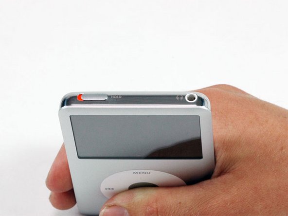
Apple designed their new iPods to be very difficult to take apart without destroying major components. Because of the metal faceplate, the metal backing, and the 13 (yes, 13) metal clips holding the case together, this is one of the toughest iPods to disassemble.
-
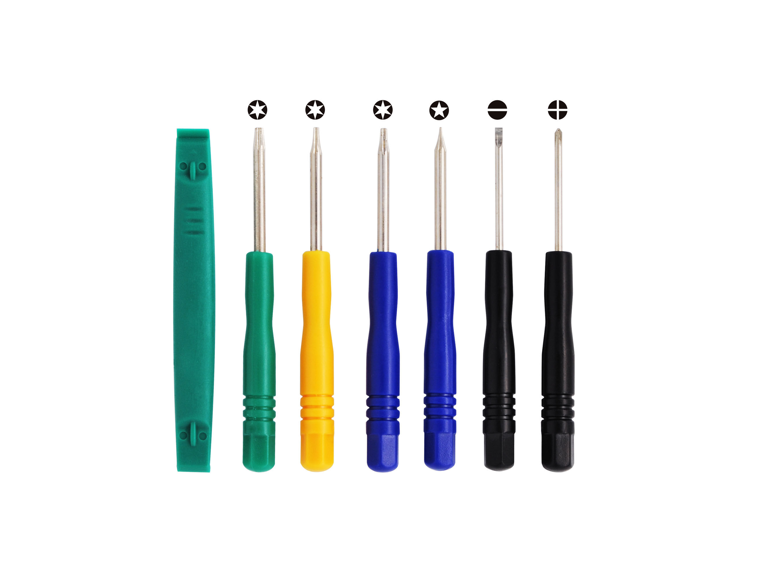
Proceed with caution and the warning that you may significantly damage your iPod beyond its present condition. Also, you may want a few extra pairs of plastic opening tools during installation, as they are easy to ruin when opening the iPod. Have fun!
|
Step 2
|
-
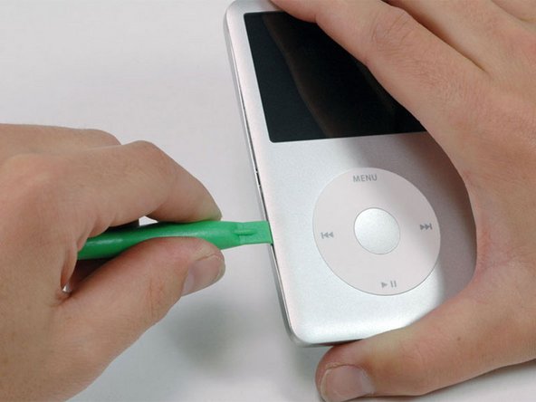
Opening this iPod is challenging. Don't get discouraged if it takes you a few tries before the iPod is opened. One thing to notice is the angle of the plastic opening tool's tip while inserting it into the iPod. Ideally, the angle should be as vertical as possible while still clearing the edge of the rear panel.
-
Insert a plastic opening tool into the seam between the front and back of the iPod.
|
Step 3
|
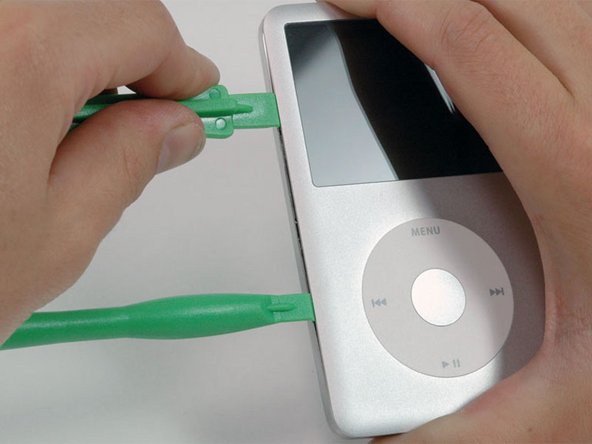
- Insert another plastic opening tool into the seam between the front and back of the iPod, leaving at least 1.5 inches of space between the two tools.
|
Step 4

|
-
At an angle, carefully insert a putty knife about 1/8 inch into the seam between the two opening tools.
-
There are thin metal rails running along the inside of the rear panel, so take great care when inserting the putty knife.
-
Once the putty knife has cleared the lip of the rear panel, pivot the putty knife so that it is vertical, and carefully (but firmly) wiggle it straight down into the gap between the opening tools.
|
Step 5

|
-
Push with your fingers on the rear panel behind the putty knife to minimize bending. Slowly flex the putty knife, as shown in the picture, to ensure that most of the metal tabs on this side of the iPod are disengaged.
-
The theory behind this method is, rather than attempting to not bend the rear panel at all, to bend it in a favorable manner that allows you to easily restore it later. Therefore, any bend in the sides of the rear panel should be drawing the lip of the rear panel away from the iPod, rather than pushing out on the curved surface. This method also disengages as many of the side clips as possible.
|
Step 6

|
-
Remove the putty knife from the iPod and reinsert it closer to the corner of the iPod, using the same wiggle method as before.
-
If at all possible, do not bend the corner of the rear panel.
|
Step 7

|
-
Between the lock slider and headphone jack, insert a plastic opening tool into the seam between the front and back of the iPod.
-
You may find it easier to carefully flex the putty knife downward in order to create more of a gap for the opening tool, but be sure not to bend the corner of the rear panel!
|
Step 8

|
-
Near the center of the display, carefully insert a metal spudger into the gap created by the plastic opening tool.
-
It is easy to create a noticeable bump in the rear panel here that is difficult to repair. When prying the tab free, try to have the metal spudger pivot on the edge of the rear panel rather than bending the rear panel outward.
-
Using the metal spudger, disengage the single clip on the top of the iPod.
|
Step 9

|
- Near the other top corner, insert an opening tool into the seam between the front and back of the iPod
|
Step 10

|
-
On the other side, insert an opening tool into the seam between the front and back of the iPod.
-
You may find it easier to angle the opening tool stuck in the top corner in order to create a sufficient gap.
|
Step 11

|
- Remove the plastic opening tool from the top corner and insert it into the seam between the front and back of the iPod, leaving at least 1.5 inches of space between the two tools (as done on the other side).
|
Step 12

|
-
At an angle, carefully insert a putty knife about 1/8 inch into the seam between the two opening tools.
-
Again, there are thin metal rails running along the inside of the rear panel, so take great care when inserting the putty knife.
-
Once the putty knife has cleared the lip of the rear panel, angle the putty knife so that it is vertical, and carefully (but firmly) wiggle it straight down into the iPod via the gap between the plastic opening tools.
-
Push with your fingers on the rear panel behind the putty knife to minimize bending. Ever so slightly flex the putty knife to ensure that most of the metal tabs on this side of the iPod are disengaged.
|
Step 13

|
-
The metal clips near the corners are notorious for tenaciously gripping the front panel. It is necessary to disengage these clips in order to open the iPod.
-
Carefully insert a metal spudger into the area near the stubborn metal clip.
|
Step 14

|
- Gently wiggle the metal spudger down so that it is all the way in the rear panel.
|
Step 15

|
-
Gently begin to disengage the clip from the front panel.
-
It is easy to create a noticeable bump in the rear panel here that is difficult to repair. When prying the tab free, try to have the metal spudger pivot on the edge of the rear panel rather than bending the rear panel outward.
|
Step 16

|
- Continue to push up on the front panel with the metal spudger until the metal clip releases.
|
Step 17

|
-
There are two ribbon cables connecting the rear panel to the rest of the iPod. In the following step, be careful not to damage these ribbon cables.
-
Grasp the front panel assembly with one hand and the rear panel with the other.
-
Take a deep breath!
-
Gently (GENTLY) disengage the remaining clips on the rear panel by pulling the tops of the front and rear panels away from each other (think of the bottom of the iPod as a hinge), taking great care not to damage the ribbon cables holding the two halves together.
|
Step 18
|
|
Step 19

|
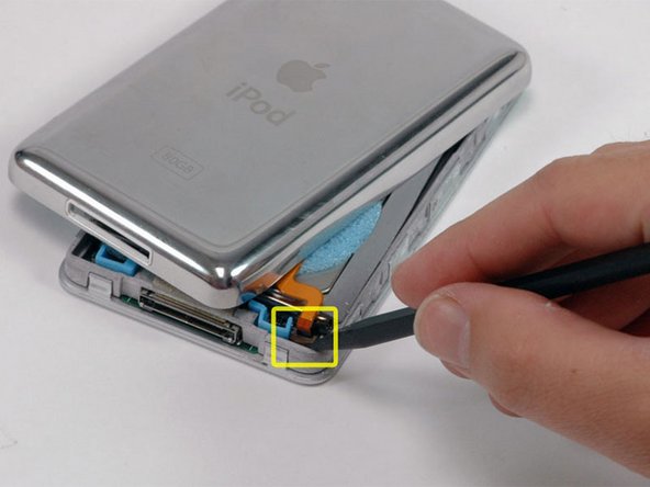
- Place the rear panel next to the iPod, being careful not to strain the orange headphone jack cable.
|
Step 20

|
-
Lift the hard drive up with one hand so you can access the headphone jack ribbon beneath.
-
Use a spudger to flip up the plastic tab holding the headphone jack ribbon in place. The tab will rotate up 90 degrees, releasing the ribbon cable.
-
Slide the orange headphone jack ribbon out of its connector.
-
The rear panel is now free from the iPod.
|
Step 21

|
- Now to repair the damage caused by liberating the internal parts of the iPod Classic! It is highly likely that at least one of the metal clips in the lower case has been bent upward. These clips must all be pointing downward in order to reinstall the rear panel.
|
Step 22

|
-
Take the broad, flat side of the metal spudger and push the clip down, taking care not to tear the thin metal rail from the rear panel. Alternatively a pair of flat pin nosed pliers can be used to reduce risk of slipping and damaging the headphone jack.
-
Be careful not to damage any of the headphone jack parts while shaping these clips!
|
Step 23

|
-
The battery is attached to the rear panel with adhesive. Be careful not to tear the orange headphone jack or hold button ribbon cables when removing the battery.
-
Use a spudger to lift the battery and the attached orange cable out of the iPod. If you have a 160 GB iPod, the battery will be thicker than the one pictured.
|
Step 24

|
-
The battery is attached to the rear panel with adhesive. Be careful not to tear the orange headphone jack or hold button ribbon cables when removing the battery.
-
Use a spudger to lift the battery and the attached orange cable out of the iPod. If you have a 160 GB iPod, the battery will be thicker than the one pictured.
|